Next, we are
going to show you how an inverter circuit is connected. Please read
through the steps carefully and we will show you how the components look as you
insert them into a circuit board. Before we do that, you need to
understand how the chip is wired internally. Here is the
pin-out for a typical 741 op-amp in a
DIP
(Dual
In-line
Package).
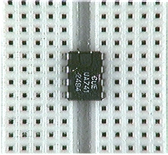
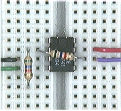
Insert the op-amp into the
circuit board. Put the chip on a circuit
board. Insert the chip so that it "straddles" the groove down the middle
between two sets of pin connector holes. It should look like the picture
below. Note that if you didn't straddle the groove, you'd connect two pins
together. Here's the amplifier in the circuit board. Notice that the
notch is toward the "top".
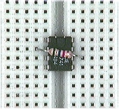
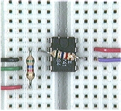
Connect the feedback resistor,
R0. Connect R0
between pin 2, the inverting input, and pin 6, the output pin. Often, you
can "bridge" the operational amplifier, that is you can just place the resistor
above the operational amplifier between pins 2 and 6 as shown on the right
below.
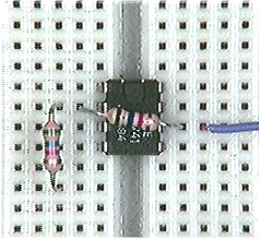
Connect the output signal lead.
Connect a lead to the output of the operational amplifier. This lead is
where you can see the output of the circuit, with an oscilloscope, for example.
Connect the input resistor, R1.
Connect power supply and ground
leads.
Remember that you have to
ground the non-inverting input. That's the next connection.
Connect the input signal lead.
Finally,
if you want to, you may proceed directly to the section on testing the
circuit. Click here if you want to go to the section on testing the
circuit. Otherwise, you should be ready to go. Check all the
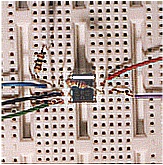
connections made in the first four steps. When you are sure you have
it correct, then you can turn on the power supplies and begin testing your
circuit. Below there's a photo of a completed circuit, and a hotlink
to take you to the section on testing the amplifier.
Testing Your Circuit
Here's the circuit again. We'll step through what you need to do to check
that you have the circuit wired correctly.
Step 1:
At this point you have your circuit connected and you believe that it is ready
to be used. You need to test your circuit to be sure that it is working.
Let's look at some things you can do.
Check the wiring! Draw
the circuit, and line out each component as you check it, and make sure each
component is connected to the correct terminal on the OpAmp.
Step 2:
Apply the power and see if it
smokes! Actually, you should apply the power and make sure that the
voltages at the pins are correct. Pin 7 should be +Vc, Pin 4
should be -Vc, and Pin 3 should be zero, all when measured with
respect to ground. (Vc is the power supply voltage!)
Step 3:
After you're sure that the
connections are correct and that the voltages are power supply pins are OK, then
you can check how the circuit behaves by using a test signal input. You'll
need a signal generator/function generator to generate a test signal, and an
oscilloscope or a voltmeter to measure the input and output signals. It's
better if you have an oscilloscope so that you can see the input and output
signal waveforms. Connect them as shown below.
Step 4
Set the function generator so
that the input has a magnitude that will produce an output less than 10 volts.
In the circuit below, R1 = Rf
= 2700W
, so
the gain is -1. Consequently, an input sine wave with an amplitude of five
(5) volts should produce an output of five (5) volts with a 180o
phase shift. Measure input and output to be sure that your circuit has the
right gain. If you have different resistor values, compute the gain and
check that your gain is right.
Step 5
You need to measure both the
input and the output. The connection to the oscilloscope below shows it
connected to the output. The dotted connection shows where you would need
to shift the oscilloscope lead to measure the input.
Some Practical Considerations
Whenever you use an operational amplifier, the power supply voltages limit the
output voltage. Let's go back to the inverter circuit we considered in
this section. Let's assume that we have an inverter with a gain of -2.
(That is, Ro/R1 = 2.) If V1
= 5.0 volts, we would expect the output voltage to be -10. volts. That's
probably OK. However. if V1 = 10.0 volts, then we might expect
the output voltage to be -20. volts. But, the output voltage can't be -20
volts. If you have power supply voltages of +/-12, it can only go as
low as -10.5 or so, so that's what the output will be, -10.5 volts.
We
have to conclude that the output voltage is always limited by the supply
voltages, and try as we might, we can't make the output voltage go outside
the limits set by the supply voltages. If we were to build an inverter
circuit, with a gain of -1, then a plot of output versus input has to look
like the one below. Without power supply limitations we would expect a
straight line with a slope of -1, and we would not expect the saturation
characteristic found below for the plot of output against input.
The net
result is that whenever the input voltage is such that it would drive the output
voltage beyond the rails, the output voltage gets clipped (does not reach a
value higher than the saturation value!), and never reaches the desired value.
This produces distortion in the output voltage when you try to amplify voice or
music signals, for example distortion that can be heard. You'll have to
have earphones or speakers connected to your sound card to hear this.
Notice the difference in the two sounds. Even
though the two sounds have just about the same amplitude the clipped sound
is harsher than the pure sine signal. That's the effect of the "hard
limiting" - the clipping - of the saturation in an operational amplifier.
What If Questions
The
operational amplifier is a versatile circuit element, and is used in many
different ways. There are many ways that the op-amp is used, and many of
them involve variations on the basic inverter circuit. Now that you've
examined the inverter circuit pretty exhaustively, we can start to look at other
possibilities. First, let's consider what some of those possibilities
might be. Here's the circuit again. Think about what could be
changed.
You can change either of the
resistors - the input resistor and/or the feedback resistor. See below.
You could - for example - substitute other electrical elements where the two
resistors appear in the basic inverter circuit.
Problems &
Questions
Q2.
Which devices can be used in place of the input and feedback resistors?
There are other possibilities for changes that could be made in the inverting
circuit. Did you think of using two input resistors like this circuit?
This is
actually a version of a widely used circuit, and it's important enought that you
should understand how it works. This circuit is interesting because it has
two (!) inputs and the output is going to depend upon both of those inputs now.
We're going to ask you to try to analyze this circuit and determine exactly how
the output depends upon those two inputs.
You
will need to plan how you will analyze this circuit. How can you analyze
the circuit? Where do you start? It will be helpful to check what
you did when you analyzed the inverter circuit. There were some important
assumptions you made. They're shown again below. Will they help you
this time? Are they true in this circuit?
The output voltage, Vout,
is within the value between the positive and negative voltage supply. It's
a "reasonable" value.
The input difference, (V+
- V-) is small enough that we can consider the value to be
approximately zero. This is due to large gain of the amplifier - the
infinite gain assumption. We will assume that
the input voltage difference is zero.
Since we will treat the input
difference as zero, and assume input resistance (the resistance between the
non-inverting and inverting inputs) is infinte, then the current flowing through
both of the inputs of the amplifier will also be so small that it is negligible.
We will assume that no current enters the input terminals of the op-amp.
If these
assumptions are true, it will help us a lot because then we can assume that the
input voltage (at the node with the red dot in the circuit diagram) is zero.
Then you can write KCL at the node with the red dot. Maybe that red dot is
Rudolph's nose, and he's bringing you a present for the holiday season!
At this
point it is up to you to finish the analysis of this circuit. You should
plan what you're going to do. Here's an approach we recommend.
Write KCL at the non-inverting
input node to the OpAmp (the red dot in the figure).
Solve for the output voltage in
terms of the two input voltages and the various resistors.
Finally, there is one other "What if?" question that many people raise.
Here's the question:
What if you reversed the two
inputs? Does that matter, and will if affect how the circuit works.
Doing that for an inverter, you would have the situation shown below.
If you
examine this circuit carefully, it is still possible to miss the fact that the
two inputs have been reversed. The inverting input is grounded, and the
feedback, through Ro, is to the non-inverting input.
That's a change from what we have been doing.
Does this make a difference? Yes, it makes a major
difference. This circuit has positive feedback, and that may mean
the circuit is unstable. It could oscillate or it could hang up at
a saturation limit. There's even an outside chance that it will work, but
it probably won't. That's a much more advanced topic, and you can click
here if you want to examine why the circuit is unstable, but you may need to
work through material on circuits, Laplace transforms, linear systems, and more,
to understand the argument.
One
last point is that even our original circuit - with the input polarities correct
- might not work. It all depends on the frequency response of the
operational amplifier, and there are some special-purpose operational amplifiers
that don't work in some simple circuits. The author has had that
experience, and it's tough to figure out what is going wrong. So, if you
connect an op-amp circuit and it doesn't work as you predicted, you probably
didn't connect it correctly, but there's a small, non-zero, chance that you did
everything right and it's just not going to work. However, for the
circuits we discuss, using a 741 style op-amp will almost always result in a
circuit that works - if you connect it correctly.
Summary:
At this
point you've looked at one operational amplifier circuit and done a little
thinking about how you could make it into something else. That's a good
start on operational amplifiers. You've learned a little about how to
analyze operational amplifier circuits and the kinds of assumptions you often,
but not always, make when you work with those circuits. You have the basic
knowledge you need to go on. Here's hoping that you continue to have fun
in this area. Build the circuits. If you overheat a 741 or two it's
no big deal. Learn and have fun.
Problems & Questions
Q3.
What kind of an amplifier is an operational amplifier?
Q4.
What is a typical gain for an operational amplifier like a 741?
Q5.
Who was the individual most responsible for the development of the integrated
circuit operational amplifier?
Q6.
What are typical power supply voltages for a 741?
Q7.
What are typical limits for the output voltage of a 741 when operated with +12
and -12 volt supplies?

 Print
Print