|
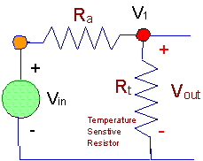
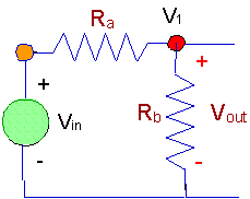
Clearly, in this circuit, assuming we make a wise choice for Ra,
we can produce a circuit with an output voltage that depends upon temperature.
We can conclude that we could use this circuit to measure temperature, or at
least to obtain an output voltage that is temperature dependent and which can be
translated into a temperature value.
Let's look at the issue of choosing Ra and the source voltage,
Vsource. Let's start by working with a 5v source.
That's a common value for a source voltage, and there's lots of power supplies
that can supply 5v. Next, we need to choose a value for Ra.
At this point, we're going to make an arbitrary decision. We'll choose Ra
so that the output voltage,Vout, is half the source voltage,
i.e.2.5v, at room temperature (25oC). That means Ra
= 5000W .
Now with a value for Ra, we can calculate the output voltage
at some different temperatures. First, we'll calculate the output voltage
at 0 oC where the resistance, Rt, is 16,330W .
What actually happens is that the thermistor resistance goes up as the
temperature goes down, and when the thermistor resistance goes up, the output
voltage goes up in this voltage divider configuration.
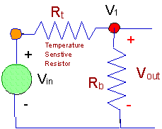
Q4.
In this circuit, as the temperature decreases from 25 oC to 0
oC will the output increase or decrease? The only difference is
that the thermistor - the temperature dependent resistor - has been put in the
other position in the voltage divider circuit. For purposes of argument,
you might want to assume that Rb
= 5000W,
so that you can compare things with the previous situation.
Now, let's look at the situation at 50 oC where the
resistance, Rt is 1801W .
You should be able to use the voltage divider formula again to calculate Vout
when Ra, is 5000W ,
and Rt is 1801W .
And remember that we are back to discussing the original placement of the
thermistor, i.e. the circuit below. (Shown just to refresh your memory.)
Let's draw
a few conclusions.
There are many variations on the measurement circuit we've discussed. You
can stop here, or you may wish to examine circuits which have two voltage
dividers embedded in them. Those are bridge circuits - a subject of
another lesson.
Using a Voltage Divider to Sense a Light Signal
Here's another voltge divider circuit. In this case there is a light
sensitive resistor, RL. The light senstive resistor has two
values. In the dark it has a resistance, Rdark
= 500,000W
(500kW ).
In the light it has a resistance, Rlight = 1000W
(1kW ).
It is exposed to both light and dark at different times, and it is desired to
have a circuit that will give a large signal - close to 5 v - when the sensor is
exposed to a dark situation, and a small signal - close to 0 v - when the sensor
is in the light.
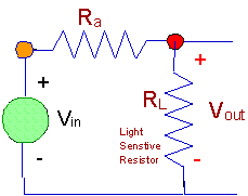
The problem here is to produce the best possible logic signal at the output
voltage terminals.
A typical set of values for a logic signal is zero volts (0v) for a logical "0"
and five volts (5v) for a logical "1". Let's assume that we use a souce
voltage of 5v. Then, in the dark, the voltage will be relatively large -
because the sensor dark resistance is large. In the light, the voltage
will be relatively small - because the sensor light resistance is small.
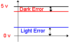
Here is the situation shown in a graph.
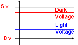
In this situation, there are two errors. One error is the amount by which
the dark signal misses being a logical "1" when it is dark. The other
error is the amount by which the light signal misses being a logical "0" when it
is light.
There's the possibility of a dilemma here. We might minimize one error and
end up making the other error very large. Clearly, we want to make both
errors as small as possible. The one thing we can choose is the value of
the constant resistance, Ra.
In order to start somewhere, let's look at the possibility of adding up the size
of both errors and minimizing the total. We'll express our terms
symbolically as much as possible as we do this. Note the following.
-
The error in each case can be
interpreted as the voltage across a resistor.
-
When we have the dark situation
we want five (5) volts across the output - the photoresistor - but if the entire
five voltage does not appear there, the difference - the error - appears across
Ra.
-
The voltage across Rais
given by:
-
When the sensor is in the
light, the error in the voltage output is actually the voltage across the
sensor, since any voltage there that is non-zero is an error. In that
situation, the voltage across the photoresistor is given by (and remember we
need to use the light resistance):
Now, there is only one thing that can be adjusted to
optimize this situation, and the thing you can change is the resistor,
Ra. Previously, we have noted that
Ra is constant. Once you choose it, it does not change
value, but you are free to choose a value for it. The photoresistor will
change resistance depending upon the light it "sees".
So, our problem is to adjust Ra so that we have the best
situation. Ideally, we would like to make both errors zero, but since Ra
has to be finite (non-zero and not infinite) we are never going to have a
situation without some sort of error. We have to decide on a measure of
how well we are doing, and we can't just take one error or the other. One
possible definition of what to minimize is to add the two errors together and
minimize the sum. There's nothing that specifically points to that, but it
seems reasonable to choose that as a measure of the total error. Here's
what we want to minimize.
At this point we have defined a problem. While there are other ways we
might have defined the problem, we have this definition to a point where it is
possible to determine a "best" value for Ra. The "best"
value for Ra is the value that minimizes the "TotalError", as
we have definted it.
There are a number of ways that you can minimize TotalError. Here are two
ways.
-
(Numerical Method)
Assume values for the light resistance, dark resistance and source voltage.
Then plot TotalError as a function of Ra.
-
(Analytical Method)
Using the analytical expression for TotalError as a
function of Ra, differentiate and find the value of Ra
that produces minimum TotalError, then evaluate the minimum.
Solving the problem using the first method isn't too hard. Shown below is
a MathCad plot of the TotalError function for:
-
Vs = 5v,
-
Rdark
= 500,000W
(500kW ),
-
Rlight
= 1000W
(1kW ).
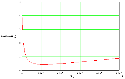
There's a pretty broad minimum in this function, and it looks like the minimum
is somewhere a little above 20kW .
To get the minimum more accurately will require more details of the calculation
(more points, and expanding the plot around the minimum so you can see it
better) or an analytical approach.
You're pretty much done with this problem. You need to consider a few
other things that might be important.
-
Maybe it's more important to
get close to zero volts than to five volts. How would you modify the
problem to take that into account?
-
What would you do if you chose
the best possible resistance, and you still couldn't get close enough to the
logic values to make it work?
-
What if you have a thermistor
instead of a light sensor? Would you still be able to produce a circuit
that gives the right values of logical zeros and ones for situations when the
thermistor is hot or cold?
-
What happens if the measuring
device attached to the circuit draws a current?
Practical Voltage Dividers
One of the most common voltage divider is the one used in volume and tone
controls in stereos, radios and televisions. That form of the voltage
divider is based on a rotary potetiometer. Most of the time when a rotary
control is used for something it is a variable voltage divider that is being
used. For example, the following are often voltage dividers in action:
-
A volume control on a radio,
stereo or television
-
A dimmer switch on a light
-
The intensity control on a CRT

Here is a sketch of a rotary potentiometer. It has several important
parts. In this sketch, each
-
A circular piece of resistive
material. It might be a conducting polymer, but it could be wound wire.
In the sketch above you might imagine the conducting material (black) to be
carbon embedded in something so that you get a smooth conducting film
-
There are connections to both
ends of the conducting material - which does not make a complete circle.
-
A slider arm that makes contact
with the resistive material. The slider arm can be rotated around a pivot
at the center, and has a separate connection wire.
This is what is inside many
volume controls, intensity controls, etc. Here is a sketch of a battery
connected to a rotary potentiometer
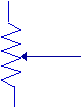
The schematic symbol for a rotary potentiometer is the same as for a linear
potentiometer, and is shown below.
-
The resistive material is
represented by a resistor.
-
The slider arm is represented
with an arrow that taps into the resistive material.
-
The arrow is intended to
represent something that can be set to various positions.
Let's consider a practical example of a potentiometer. Here's a sketch of
a battery attached to a rotary potentiometer and a voltmeter attached between
the slider arm and one end of the potentiometer.
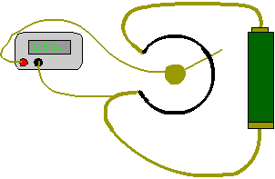
You should be able to see
that when the slider is all the way clockwise (in the 8 o'clock position), there
will be no voltage across the voltmeter. When you crank the slider
completely the other way (in the 10 o'clock position) the full battery voltage
will appear across the voltmeter (about 1.5 volts). In the position shown,
a fraction of the battery voltage is measured by the voltmeter.
You have seen rotary potentiometers used many times as volume controls in audio
equipment, radios, etc. Instead of a battery, the source might be a
microphone or some other audio signal, and the size of the signal that is
transmitted - ultimately to be heard - depends upon the setting of the
potentiometer.
Finally, you should notice that the total resistance always stays the same in a
potentiometer, so that if you want to model the potentiometer as an adjustable
voltage divider you will always have Ra + Rab
= Rtotal some constant value that is the resistance you would measure
if you measured the resistance from end-to-end with nothing else connected to
the potentiometer. Our conclusion:
What Does A
Voltage Divider Look Like?
Here is a drawing of a voltage divider built on a circuit board.
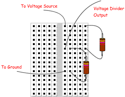
This
circuit corresponds to the circuit in this circuit diagram - assuming that the
bottom (negative) end of the input voltage source is grounded. The output
voltage is take from the midpoint between the two resistors above. And,
remember, that each group of five terminals is really a node.
|


