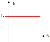
Notice that an ideal current source is somewhat similar to an ideal voltage
source. However, when you use an ideal source - usually when doing circuit
analysis- there is a significant difference in the analysis. However,
that's getting ahead of the story. We first have to worry about how you
would "use" an ideal source, when we know that there is no such thing as an
ideal source, i.e. a source that is "perfect" in some way.
Using Ideal Sources
The idea of using ideal sources is something that you may rebel at. After
all, there is no such thing as an ideal source anywhere in the world. You
can't pull an ideal source off the shelf in the lab, so why are we even talking
about them? The answer to that question is that you use ideal sources when
you have a non-ideal (a real source) source in a circuit. There are two
important things to note.
-
There are some sources that are very
good sources and that can be modelled as ideal sources. (And when that
happens, be grateful.) Some situations like that include the following.
-
A power supply in the lab. Many
times you connect a power supply to some electronic circuit, for example, and
when you connect the circuit you find that the output voltage from the power
supply doesn't change measurably. (After all, power supply designers try
to make that happen!) In that case, the power supply might be considered
to be an ideal source - at least as long as you are working on that particular
circuit.
-
There are many sources that do not
perform ideally. However, it has proven to be possible to construct
models
of real sources, and those models often contain ideal source in combination with
other ideal elements (like resistors, etc.).
Thevinin
and
Norton equivalent circuits are examples of models of real sources that can
account for loading effects (i.e. drawing enough current from the source to
change the output voltage) and they are widely used in circuit analysis.
You will even find that manufacturers give you parameter values for Thevinin and
Norton equivalents on the front panel of many instruments like function
generators.
You often have situations in which the sources that you use can be approximated
with ideal sources. Shown below is a bridge circuit powered by a battery.
Often a battery maintains a pretty constant voltage across the terminals, so you
may be able to replace the battery with an ideal voltage source when you analyze
the circuit.
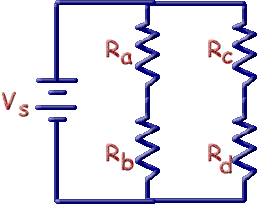
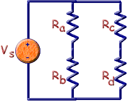
Here's the circuit with an ideal voltage source substituted for the battery.
At this point, you may know how to do the analysis so you're ready to go.
If you don't know how to do the analysis, you'll get there in these lessons.
More On Using Sources - AC Sources
You've used AC sources many times. Every time you plug anything into a
wall plug you are using an AC source. That source - the wall plug - is
designed to be a good voltage source - to maintain the voltage without change -
as current is drawn from the plug. The power company makes a lot of effort
to ensure that you have a reliable, known voltage at the wall plug. You,
and all the manufacturers that make things to plug into wall plugs, depend on
that voltage being what it is claimed to be.
It's important to understand how that source is used because it is much like the
way many other sources are used. You've plugged many things into wall
plugs. Have you ever considered how those plugs are wired. The
diagram below depicts how wall plugs are wired. (We haven't used the
standard code for colors for house wiring since that involves a wire that is
white that wouldn't show up here.)
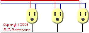
Two wires carry the voltage to the
plug - shown in red and blue above.. The voltage difference between these
two wires is approximately:
170 * sin(2p60t).
Notice that the three wall plugs illustrated below are actually wired in
parallel so that the same voltage appears across
the three plugs. Because they are in parallel
and the voltage is the same for each plug we are actually counting on the source
that drives this circuit to be a good voltage source - as close to an ideal
voltage source as possible. Every article that gets plugged into the wall
plug is designed to operate on the voltage that appears across the plug, so it
is reasonable to expect the same voltage at every plug.
Note that we are not claiming that the voltage is always the same at every time
in the situation above. Rather, for any given time, the voltage across all
of the plugs is what we want it to be for that particular time. As time
goes on, for the wall plug, the voltage we want to have varies sinusoidally.
Whenever you wire things in the lab you'll find the same kind of thing
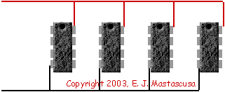
happening. Here's an illustration of using a +5 volt supply to power three
integrated circuit logic chips. Each chip needs five (5) volts. Each
chip draws current. The power supply should be designed to provide 5 volts
(the red lead(s)) no matter how much current is drawn up to some limit.
It's designed to be as close as possible to an ideal voltage source as it can
be.
Conclusions
There are some conclusions to be drawn here. Many devices - from large
appliances to IC chips - are designed to operate at specific voltages. The
sources the supply power to these devices therefore have to be designed to
supply constant voltages so they will be as close to ideal voltage sources as
the designer can get them. The flip side of all this is that when you want
to use these devices you need to ensure that you apply the correct voltage.
You do that by connecting the devices in parallel - and not in series.
There are undoubtedly other lessons about sources that you will learn in your
electrical engineering career (and some may be bitter and hard-learned indeed).
What If The Source Isn't Ideal?
That's a tough problem. You know that there are sources that aren't ideal.
In the lab voltages change when you attach components. In your car, the
lights dim when you start the car with the lights on. These are examples
of non-ideal sources in the real world.
To deal with non-ideal sources you can use
Thevenin Equivalent Circuits or
Norton Equivalent Circuits. In either case you will find that a
component of the equivalent circuit is an ideal source - even though the
equivalent is used to represent a non-ideal source. Go to that lesson to
find our how that all comes about.
|


