AC instrumentation transducers
Just as devices have been made to measure certain physical quantities and
repeat that information in the form of DC electrical signals (thermocouples,
strain gauges, pH probes, etc.), special devices have been made that do the same
with AC.
It is often necessary to be able to detect and transmit the physical position
of mechanical parts via electrical signals. This is especially true in the
fields of automated machine tool control and robotics. A simple and easy way to
do this is with a potentiometer: (Figure
below)
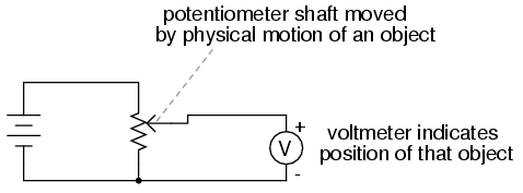
Potentiometer tap voltage indicates position of an object slaved to the
shaft.
However, potentiometers have their own unique problems. For one, they rely on
physical contact between the �wiper� and the resistance strip, which means they
suffer the effects of physical wear over time. As potentiometers wear, their
proportional output versus shaft position becomes less and less certain. You
might have already experienced this effect when adjusting the volume control on
an old radio: when twisting the knob, you might hear �scratching� sounds coming
out of the speakers. Those noises are the result of poor wiper contact in the
volume control potentiometer.
Also, this physical contact between wiper and strip creates the possibility
of arcing (sparking) between the two as the wiper is moved. With most
potentiometer circuits, the current is so low that wiper arcing is negligible,
but it is a possibility to be considered. If the potentiometer is to be operated
in an environment where combustible vapor or dust is present, this potential for
arcing translates into a potential for an explosion!
Using AC instead of DC, we are able to completely avoid sliding contact
between parts if we use a variable transformer instead of a
potentiometer. Devices made for this purpose are called LVDT's, which stands for
Linear Variable Differential Transformers. The
design of an LVDT looks like this: (Figure
below)
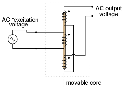
AC output of linear variable differential transformer (LVDT) indicates
core position.
Obviously, this device is a transformer: it has a single primary
winding powered by an external source of AC voltage, and two secondary windings
connected in series-bucking fashion. It is variable because the core is
free to move between the windings. It is differential because of the way
the two secondary windings are connected. Being arranged to oppose each other
(180o out of phase) means that the output of this device will be the
difference between the voltage output of the two secondary windings. When
the core is centered and both windings are outputting the same voltage, the net
result at the output terminals will be zero volts. It is called linear
because the core's freedom of motion is straight-line.
The AC voltage output by an LVDT indicates the position of the movable core.
Zero volts means that the core is centered. The further away the core is from
center position, the greater percentage of input (�excitation�) voltage will be
seen at the output. The phase of the output voltage relative to the excitation
voltage indicates which direction from center the core is offset.
The primary advantage of an LVDT over a potentiometer for position sensing is
the absence of physical contact between the moving and stationary parts. The
core does not contact the wire windings, but slides in and out within a
nonconducting tube. Thus, the LVDT does not �wear� like a potentiometer, nor is
there the possibility of creating an arc.
Excitation of the LVDT is typically 10 volts RMS or less, at frequencies
ranging from power line to the high audio (20 kHz) range. One potential
disadvantage of the LVDT is its response time, which is mostly dependent on the
frequency of the AC voltage source. If very quick response times are desired,
the frequency must be higher to allow whatever voltage-sensing circuits enough
cycles of AC to determine voltage level as the core is moved. To illustrate the
potential problem here, imagine this exaggerated scenario: an LVDT powered by a
60 Hz voltage source, with the core being moved in and out hundreds of times per
second. The output of this LVDT wouldn't even look like a sine wave because the
core would be moved throughout its range of motion before the AC source voltage
could complete a single cycle! It would be almost impossible to determine
instantaneous core position if it moves faster than the instantaneous source
voltage does.
A variation on the LVDT is the RVDT, or Rotary Variable Differential
Transformer. This device works on almost the same principle, except that
the core revolves on a shaft instead of moving in a straight line. RVDT's can be
constructed for limited motion of 360o (full-circle) motion.
Continuing with this principle, we have what is known as a Synchro or
Selsyn, which is a device constructed a lot like a wound-rotor polyphase
AC motor or generator. The rotor is free to revolve a full 360o, just
like a motor. On the rotor is a single winding connected to a source of AC
voltage, much like the primary winding of an LVDT. The stator windings are
usually in the form of a three-phase Y, although synchros with more than three
phases have been built. (Figure
below)
A device with a two-phase stator is known as a resolver. A resolver
produces sine and cosine outputs which indicate shaft position.
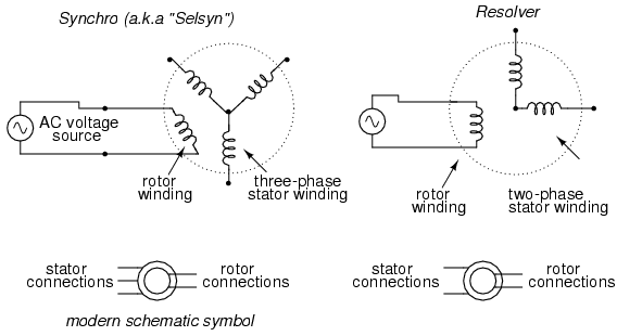
A synchro is wound with a three-phase stator winding, and a rotating
field. A resolver has a two-phase stator.
Voltages induced in the stator windings from the rotor's AC excitation are
not phase-shifted by 120o as in a real three-phase generator. If
the rotor were energized with DC current rather than AC and the shaft spun
continuously, then the voltages would be true three-phase. But this is not how a
synchro is designed to be operated. Rather, this is a position-sensing
device much like an RVDT, except that its output signal is much more definite.
With the rotor energized by AC, the stator winding voltages will be proportional
in magnitude to the angular position of the rotor, phase either 0o or
180o shifted, like a regular LVDT or RVDT. You could think of it as a
transformer with one primary winding and three secondary windings, each
secondary winding oriented at a unique angle. As the rotor is slowly turned,
each winding in turn will line up directly with the rotor, producing full
voltage, while the other windings will produce something less than full voltage.
Synchros are often used in pairs. With their rotors connected in parallel and
energized by the same AC voltage source, their shafts will match position to a
high degree of accuracy: (Figure
below)
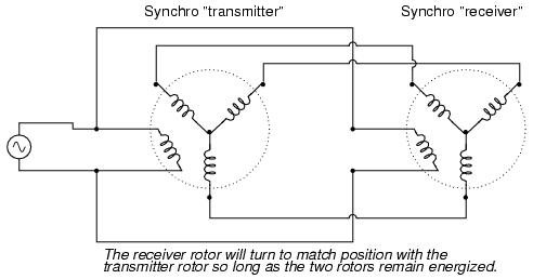
Synchro shafts are slaved to each other. Rotating one moves the other.
Such �transmitter/receiver� pairs have been used on ships to relay rudder
position, or to relay navigational gyro position over fairly long distances. The
only difference between the �transmitter� and the �receiver� is which one gets
turned by an outside force. The �receiver� can just as easily be used as the
�transmitter� by forcing its shaft to turn and letting the synchro on the left
match position.
If the receiver's rotor is left unpowered, it will act as a position-error
detector, generating an AC voltage at the rotor if the shaft is anything other
than 90o or 270o shifted from the shaft position of the
transmitter. The receiver rotor will no longer generate any torque and
consequently will no longer automatically match position with the transmitter's:
(Figure
below)
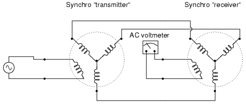
AC voltmeter registers voltage if the receiver rotor is not rotated
exactly 90 or 270 degrees from the transmitter rotor.
This can be thought of almost as a sort of bridge circuit that achieves
balance only if the receiver shaft is brought to one of two (matching) positions
with the transmitter shaft.
One rather ingenious application of the synchro is in the creation of a
phase-shifting device, provided that the stator is energized by three-phase AC:
(Figure
below)
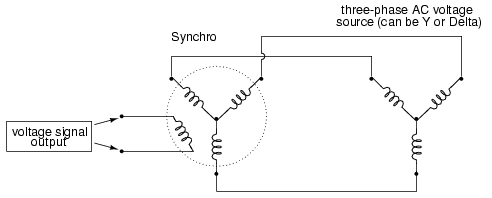
Full rotation of the rotor will smoothly shift the phase from 0o
all the way to 360o (back to 0o).
As the synchro's rotor is turned, the rotor coil will progressively align
with each stator coil, their respective magnetic fields being 120o
phase-shifted from one another. In between those positions, these phase-shifted
fields will mix to produce a rotor voltage somewhere between 0o, 120o,
or 240o shift. The practical result is a device capable of providing
an infinitely variable-phase AC voltage with the twist of a knob (attached to
the rotor shaft).
A synchro or a resolver may measure linear motion if geared with a rack and
pinion mechanism. A linear movement of a few inches (or cm) resulting in
multiple revolutions of the synchro (resolver) generates a train of sinewaves.
An Inductosyn� is a linear version of the resolver. It outputs signals
like a resolver; though, it bears slight resemblance.
The Inductosyn consists of two parts: a fixed serpentine winding having a 0.1
in or 2 mm pitch, and a movable winding known as a slider. (Figure
below)
The slider has a pair of windings having the same pitch as the fixed winding.
The slider windings are offset by a quarter pitch so both sine and cosine waves
are produced by movement. One slider winding is adequate for counting pulses,
but provides no direction information. The 2-phase windings provide direction
information in the phasing of the sine and cosine waves. Movement by one pitch
produces a cycle of sine and cosine waves; multiple pitches produce a train of
waves.
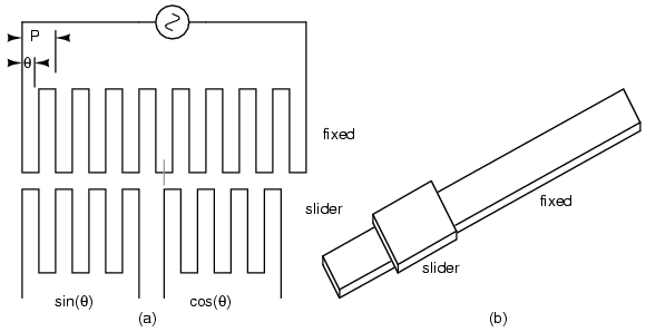
Inductosyn: (a) Fixed serpentine winding, (b) movable slider 2-phase
windings. Adapted from fig 6.16
|

